


|
|
Boost Gauge |
 \ \
The stock boost gauge is crap. Usually it is off by several psi and isn't consistent in it's readings. So, the solution for accurate pressure monitoring is to install aftermarket boost gauge. Autometer has been producing gauges as long as there has been a need for them. They sell many different versions of their gauges, with different looks and sizes. I chose Autometer's Phantom series, a white faced, black beveled 2 1/16" series that looks nice in the interior of our trucks. The gauge includes:
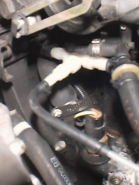
Installation: You can buy, and follow the instructions given byRon G. about his custom NTP fitting.\ or You need to "T" off of a vacuum line under the hood to provide the pressure/vacuums reading for the gauge. The best existing place to "T" is off the vacuum line in the front of the motor, under the forward side of the throttle body. T'ing off the MAP sensor/FPR could cause delayed readings to the MAP or FPR and has potential to cause problems. There are two vacuum lines in this cramped space. One goes to the evaporation canister, and the other, I believe operates the climate control vent doors. This is the one we want to T off of.
I used what I could find at the parts store: a universal T. The problem finding an adapter is you need a T that tapers down to the size of the hard line included with the gauge. The only thing available at autozone that would fit was this huge universal fitting T. We purchases a little extra Vacuum hose to connect the t to the fitting and some smaller line to connect the T to the hard line. We put the T between the point where the vacuum line was connected before, and the vacuum line that was connected to the fitting. The smaller end linked up to the smaller Vacuum line and ran to the Hard line. Inserted the hard line a good distance into the vacuum hose, and zip tied it tight.
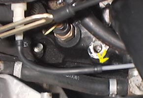
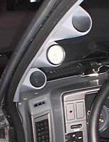
The hard line was routed along the drivers side of the motor towards the brake booster and into the grommet located on the side of it. It was then routed along the underside of the dash, and out toward the crack between the left side of the dash and the body. From there, the hard line goes up toward the A-pillar and to the gauge. Make sure to measure this length before you cut the vacuum line for your T. The vacuum line is inserted into the compression fitting into the rear of the gauge and threaded in using PPT.
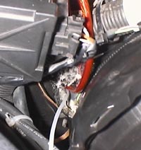
To wire the gauge's lights, you need to connect the power to the dimmer slot on the fuse box and connect the ground to ground using a variety of bolts under the dash. Below is a cramped picture of the fuse box. Crimp a flat inserting type connector onto the end of the positive feed for the gauge, and insert into the spot pictured below (blue round connector next to large red & green connectors)
once you have the power, vacuum and ground lines connected up, you should be good to go. Have fun testing ;) |